Now I finished up the last post after discovering the Sheriff game ran with the I/O board from HeliFire and possibly tracing the issue to a bank of counter ICs. Unfortunately, due to being very new to arcade repair I didn’t have any replacement parts. So off to eBay I went and ordered a variety of ICs that were used on the Sheriff I/O board.My good friend Paul was with me when we were first looking at the board and he’d tracked some incorrect signals coming from a bank of four 161 counter ICs.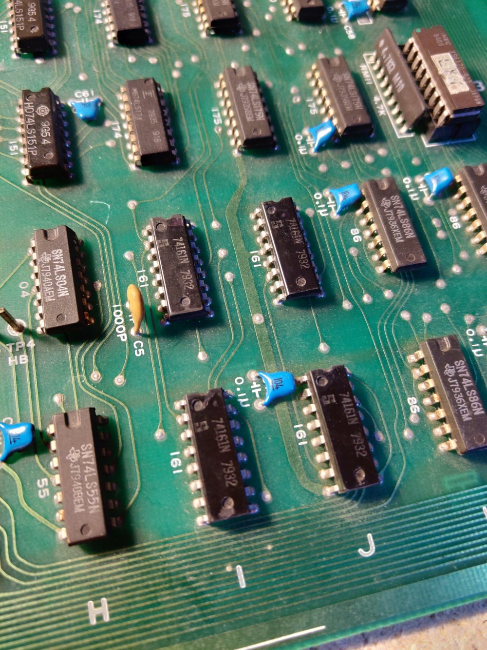 Now with these components, you can technically “piggyback” new components directly ontop of the suspected faulty components. This is the route I’d taken with the Radarscope repair when trying to trace which RAM IC had gone faulty. So after a few days, my eBay purchases had started to arrive.
 These were an odd 7 that someone was selling, but I also managed to get hold of a tube of 50 of them from Bulgaria, which according to the eBay listing were old stock from the State Military surplus!Anyway, in my true, complete lack of patience style, I “piggybacked” four new 161 counters onto the bank of four on the board. I flicked on the power and was met with a completely black screen! That’ll teach me for not working through this with patience and working methodically. So I removed all of the 161s and out one back on the first in the bank according to the schematics.
 I switched on the power and waited for the monitor to warm up.
 I couldn’t believe it! First test (if you ignore the impatient start…) and I’d got the right one. It makes sense that this was the one that had faulted as all of them were outputting incorrect signals. This made sense considering they were all fed by this one.So to prove my complete lack of patience once again, I grabbed the cocktail control panel and plugged it into the boardset.
 The game coined up, started and played. I was super happy at this point as I’d waited so long to play this game. After a couple of rounds (not the easiest whilst balancing the control panel precariously over the live PCB!) I switched off the game and turned on my desoldering station, it was time to get this repair underway.After my mishap with Radarscope, I knew I had to take my time with this boardset as getting a replacement was not going to be an easy task! I set the temperature to 350C to try and reduce any PCB burn and started work on the desoldering the legs of the faulty 161.
 Much better than last time so clearly the practice is paying off. You can see in the picture above where I’ve removed the solder from each joint and freed th legs. Next step was to turn over the board and wiggle the chip free.
 There he goes and with all traces in tact. I then inserted one of the new 161s into place, flipped over the board and soldered all of the legs.
 I need to clean the flux off of the joints, but aside from that I was happy with the soldering. I let the board cool and then reconnected everything back up to test my work.
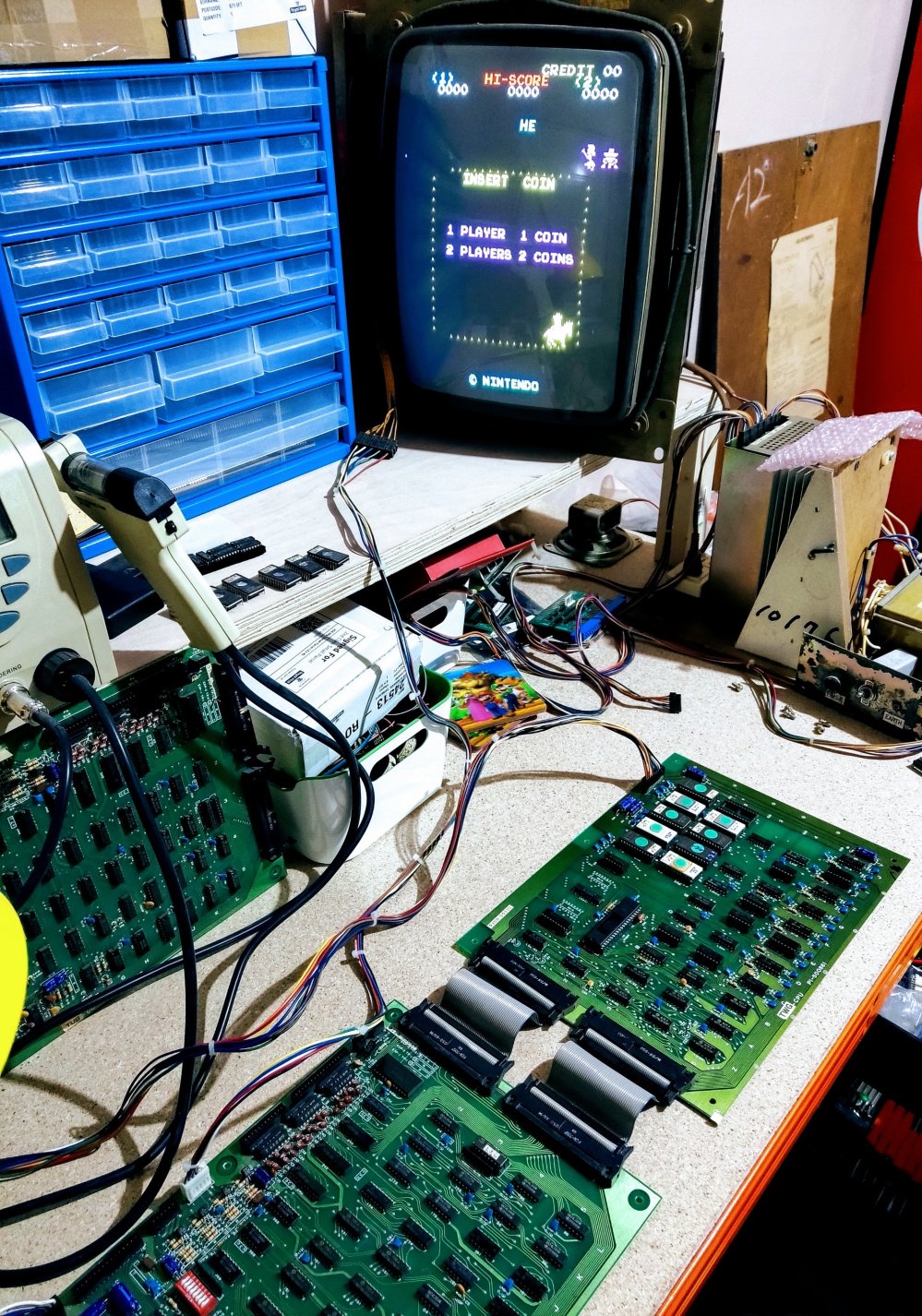

A good result. Now the only thing I hadn’t done throughout all of this was connect up the sound board. Unlike Radarscope, the Sheriff boardset will run quite happily without it connected.
I connected up the soundboard and played through a couple of games enjoying Sheriff in its full glory… or so I thought. Something wasn’t quite right. I checked a video online of the gameplay to confirm my suspicions and it appears that I’m missing the firing sound and the sound of the bullet hitting the bandit. All of the other sounds were there, so I referred back to the Bandido schematics. Unfortunately, the sound board on Bandido appears to differ quite a lot so I resorted to a set of Space Fever schematics (as the sound board is a converted Space Fever board).
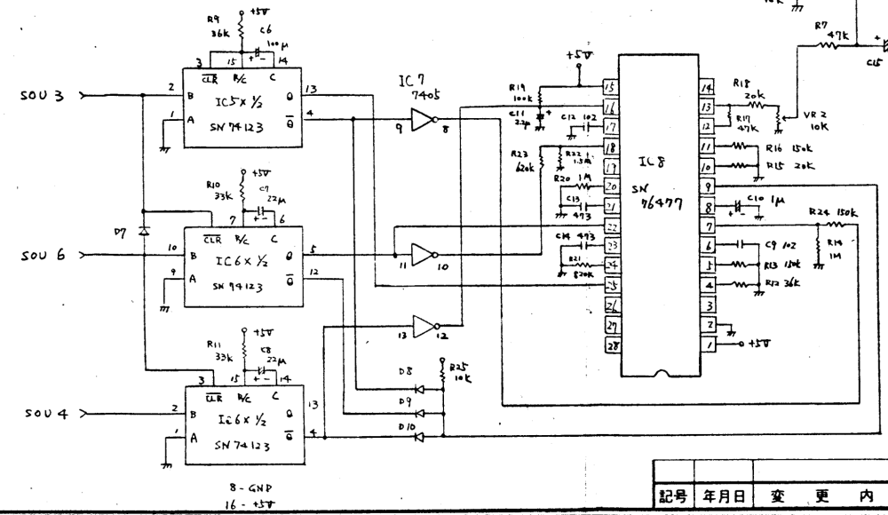
So we can see from the above that the signal for sounds 3, 4 and 6 go through to ICs. Sound 3 into IC5 and sounds 6 and 4 into IC6 (shown in two halves on the schematics. A very quick scan of the board itself helped narrow this down as there is no IC5 on a Sheriff sound board, just a blue wire bridging one of its connections to another point on the board.
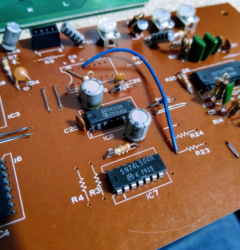
All is left to do now is to see if the soundboard is actually recieving the signal to trigger the sound. My plan is to ground the pins that these signals are supposed to come through. If it isn’t actually recieving the signal, then the fault will most likely be on the I/O board. If it is receiving the signal, then the fault is on the sound board.
So that’s where I’ve got up to. I’m really happy to have the faulty IC replaced game playing. A couple of missing sounds is annoying, but hasn’t detracted from the joy of actually being able to play the game.
