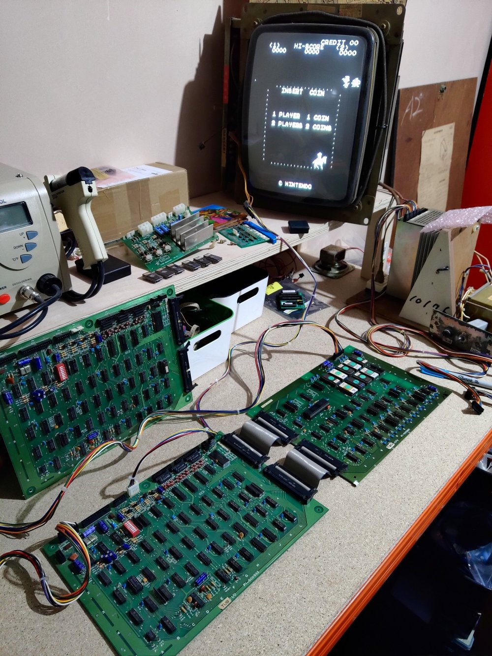
So in my last update on this restoration I had assembled the cocktail and discovered the board gave me nothing!The next step was to work with my friend Paul and try and diagnose the issue that was stopping the board booting. We had a quick look over it a few weeks back and with swapping board with Paul’s working Sheriff boardset, ascertained that the issue was with the I/O board as my CPU board worked with Paul’s I/O board and the game ran.Unfortunately, my last technical purchase of a Fluke diagnostics tool couldn’t help me as it just reported a short to the CPU when plugged in and wouldn’t go any further, so we were going to have to do this the long way. We hooked the board up this last weekend to my test bench and started work:

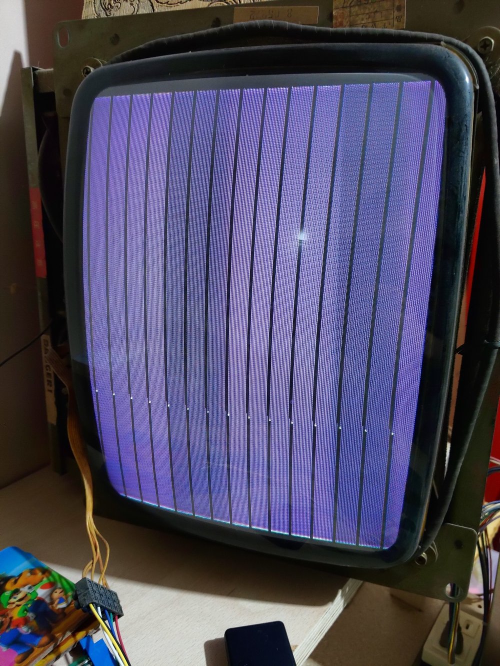
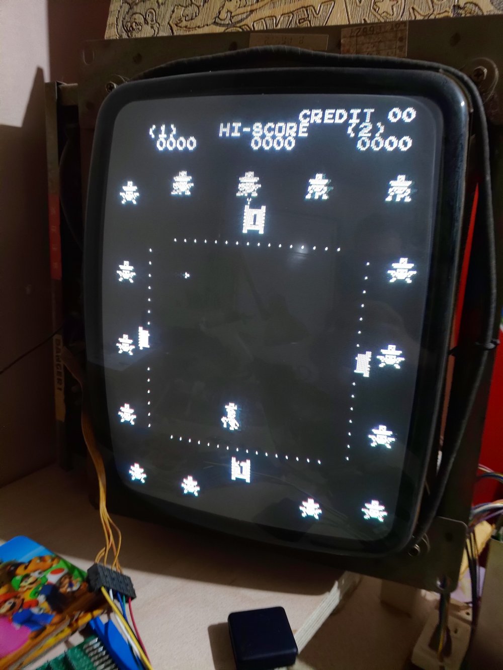
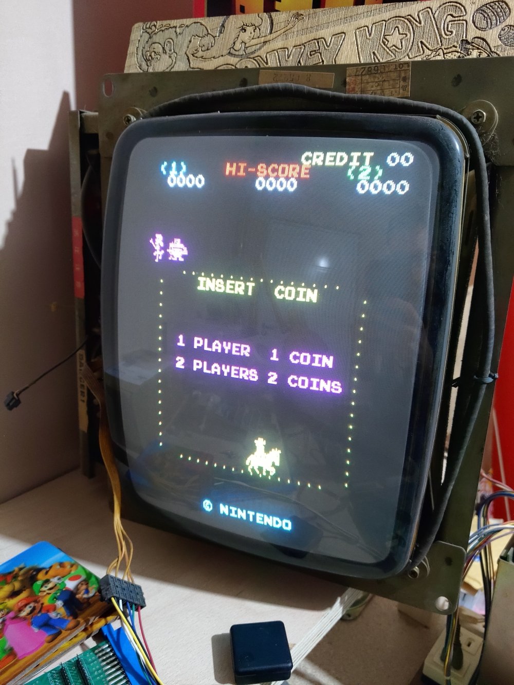
As you can see in the above picture, we’ve no miraculous change and the board still displays purple bars intersected with thin black bars containing random white dots:
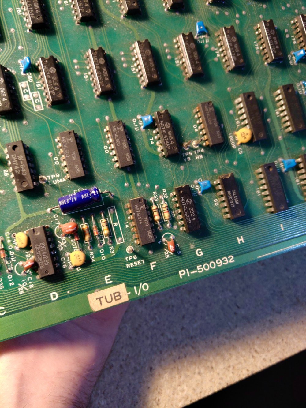
So first steps were to try and ascertain where the issue was coming from on the I/O board. We started measuring inputs and outputs of some ICs using the newly uploaded Bandito schematics (thanks Mike Haaland from MikesArcade.com) as these are the same as Sheriff and there has previously been no available schematics for Sheriff.
After some quick work with the logic probe, we started to get inputs and outputs of some suspect ICs. I’m very new to the diagnostics so I feel Paul’s pain of having to try and explain what he was looking for/seeing in “simple” terms.
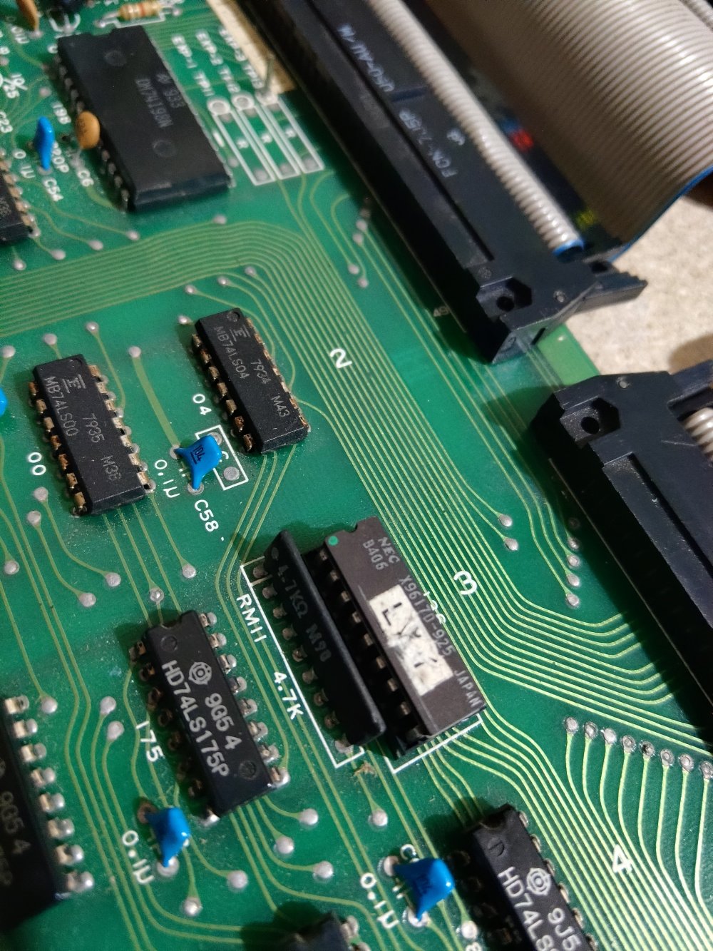
Now using the schematics, technical papers for the ICs and Paul’s knowledge, we ascertained that this bank of 161s appeared to be recieving what we believe is an incorrect signal.
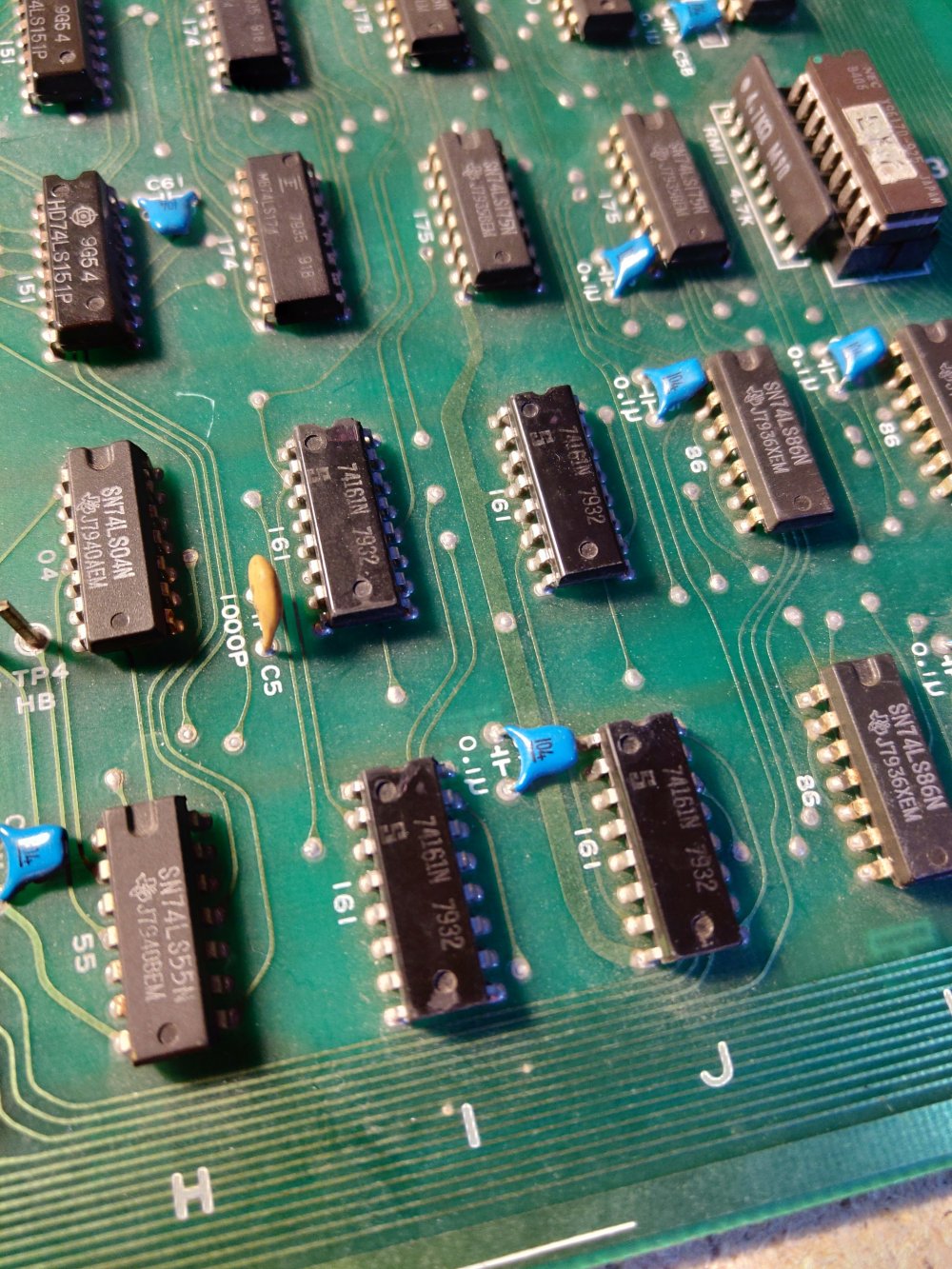
The schematics show that three of these ICs are actually fed by the fourth so either there is an issue with the IC that is receiving the signal, or the signal it is receiving. As a nice quick way of checking these chips, we could technically piggyback new ICs over the top (as I did with the RAM on Radarscope), but unfortunately, as I’m new I these technical repairs I’m also short on supplies. So I’ve got a shopping list together of a load of new ICs to allow to me to piggyback/replace any suspect ones.
In the meantime, I decided to try something that I have long suspected of the early Nintendo boardsets. We know from the famous Radarscope to Donkey Kong conversions (and many others as I started documenting) that Nintendo repurposed a lot of boards in the early days. After researching the TRS to TKG conversions I realised that my HeliFire boardset had been something else in a previous life, Sheriff!

The I/O board is the same on both games, but HeliFire has had some factory modifications:
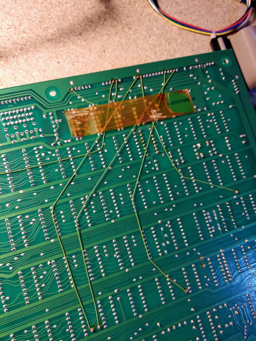
It appears a lot of those modifications are to do with the separate ESS board that drives the video and colour for HeliFire, but also the difference in inputs (Sheriff has 17 inputs whereas HeliFire has only 9).
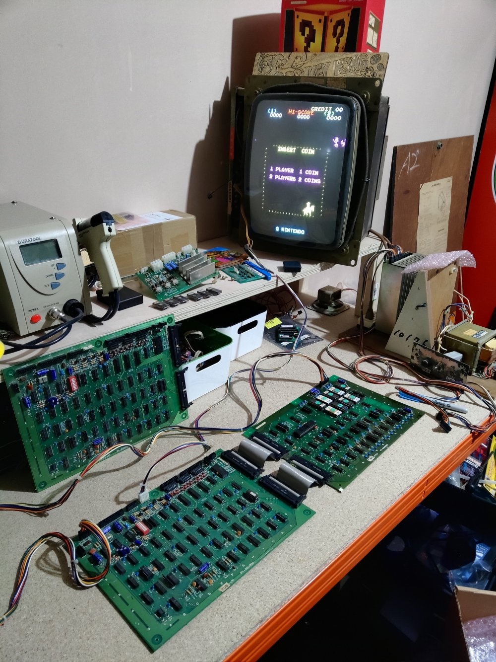
So out of curiosity, we unhooked the Sheriff I/O board and hooked up my known working HeliFire I/O board. We flicked on the power and watched the monitor flicker to life:
I don’t think either of us thought that would work, despite knowing technically that it should. No the eagle eyed will notice that the game is in black and white. The only difference between the two I/O boards (aside from the factory modifications) is a small colour PROM on the right hand side of the board:
So, as we’d come this far, we swapped the PROM over into the HeliFire board and flicked on the power:

I don’t think I can express how happy it made me to see Sheriff in all of its glory running on my test bench. All I wanted to do was plug in one of the control panels and have a quick game, but I knew this wouldn’t work due to he factory mods on the HeliFire I/O board, plus this would distract me from getting the Sheriff boardset fixed!
So the situation I’m in now means that I can use my logic probe to measure and note down all of the inputs and outputs of the ICs we suspected were faulty on the original board, plug that one back in and compare. I appreciate this isn’t the most technical of approaches, but doing it this way is helping me understand how and why things work they way they do, whilst also teaching me to read schematics.
So my next steps are to now spend a few evenings working my way around the board noting down inputs and outputs of the ICs. This should keep me busy whilst I wait for the new ICs to arrive. I promise I won’t plug a control panel in and get distracted…

This is good progress. And whilst maybe not the most efficient method, it’s exactly what I would do too, with my utterly limited knowledge. Logic will prevail!
Looking forward to the next update where it all works!
LikeLike