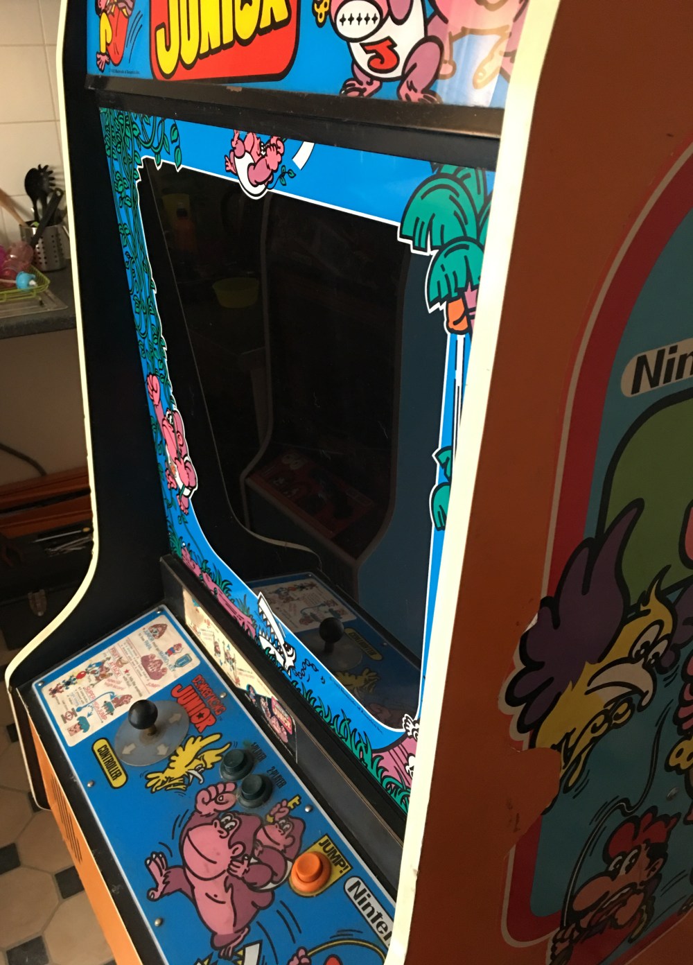
So if you’ve seen my “Purchases (Mar-Apr ‘18)” blog post, you’ll have seen I recently picked up a Donkey Kong Junior. I’ve been wanting DKJr for a while now mainly to complete my Donkey Kong trilogy, but also as a good excuse to replace the Double Donkey Kong board in my DK cabinet.
A fellow collector (Paul) was thinning out his collection by getting rid of some duplicates. He knew I was after DKJr so we came to an agreement on a good price and a few weeks later it was in my kitchen. He was unsure as to whether the PCB worked (as the power supply had popped recently), so swapped it out for a known worker. We hooked everything up and switched it on and were greeted with a scrolling screen which was heavy on red. After a few tweaks of the pots on the monitor we finally stabilised the picture, but unfortunately, the left hand side of the screen was drooped.
Our initial diagnosis was bad capacitors on the monitor so we switched it off at this point as it was getting late in the day and Paul still had a two hour drive home.
I had a spare couple of hours on a Friday evening (after the little one had gone to bed) so decided to have a tinker. I’d read earlier in the day that a drooped side of a screen could be down to B+ voltage. It wasn’t the right time to start poking around with multimeters, so I decided to just have a play with all the adjustment pots instead. Now there were a few more pots on this cab than my previous two. At some point, Nintendo added an additional board to the Sanyo monitors which would allow the input of both inverted and non-inverted images. This board had a full compliment of RGB pots:
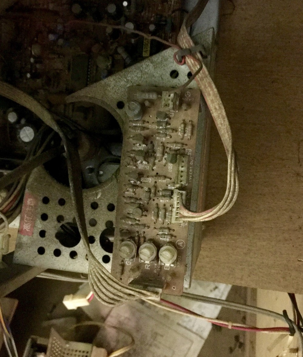
So now as well as the two pots on the main PCB and the five on the monitor control board, we had three more to play with.
As the picture was drooping on the right hand side and I assumed it could only be repaired with a capacitor replacement, I started work getting the picture centred and the right colour. As all of the adjustment pots are in the back of the cab, I kept adjusting a pot, then walking round to the front of the cab to check the picture. This proved frustrating and unproductive as the adjustments required were so small and I just seemed to be overshooting each time. My wife came in and suggested using a mirror (Paul had suggested a selfie stick!) so I could see what I was doing. One mirror propped on the CPO facing backwards and we were in business. 15 minutes later, we had a proper picture:
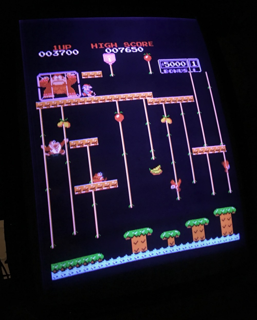
I even managed to eradicate the droop! The picture was perfect, and looked even better once I cleaned the screen itself (30+ years of baked on grime seriously dulled the picture).
Correcting the red balance took the most time as it was a while before I realised I had another set of colour pots on the neck board on the monitor. All was well now though and the colours look great.
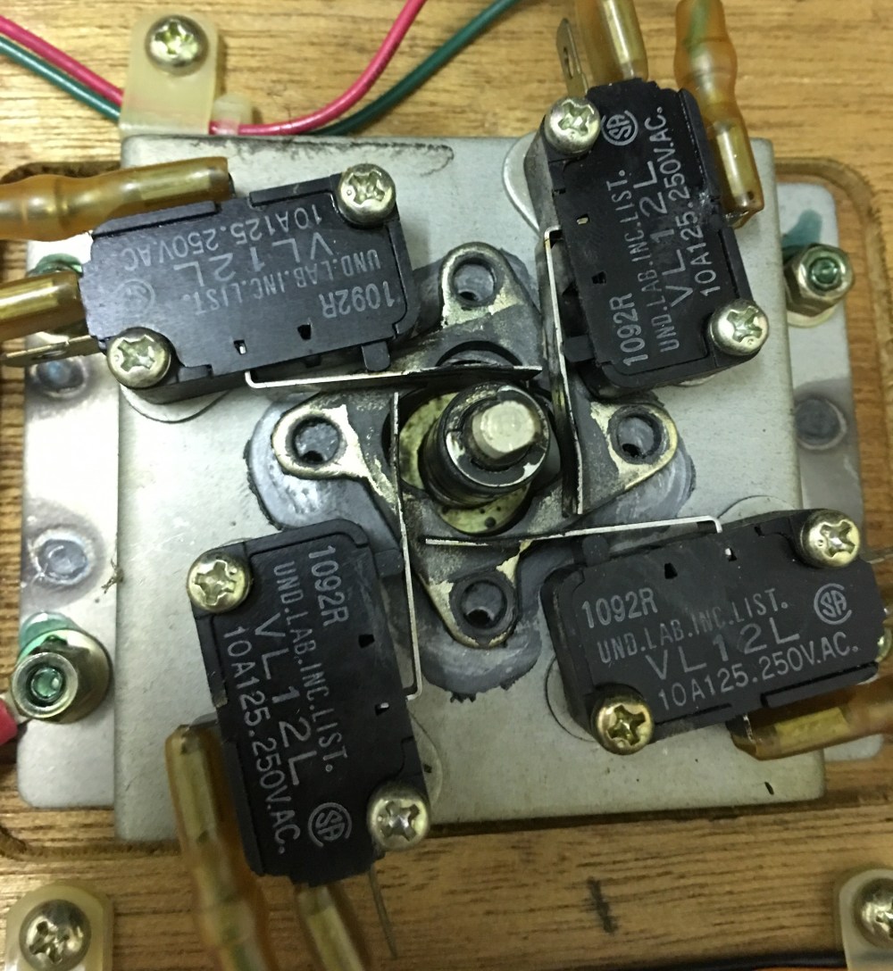
One thing Paul noticed when we powered up the monitor for the first time was a short glow from one of the fuses on the monitor chassis. It only glowed for a few seconds as the tube warmed up and then settled down. I was a little worried about this, but my concerns grew as I actually investigated the issue when playing with the monitor adjustments:
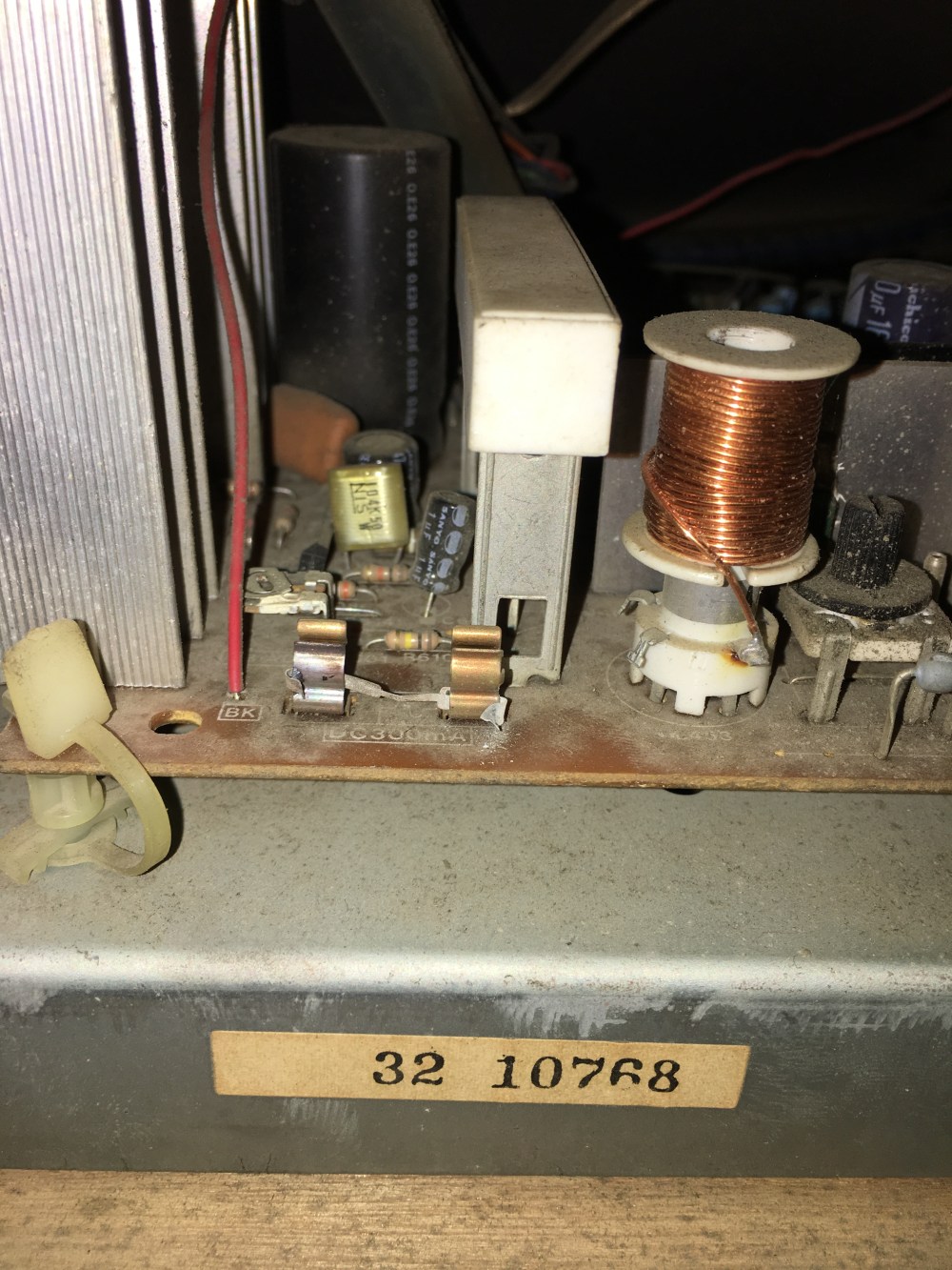
The eagle-eyed amongst you will see that there isn’t actually a fuse in the fuse holder, but what appears to be fuse wire bent around the two ends of the holder! You can probably tell from the picture above which side glows as the heat has has discoloured it. That’ll definitely need some attention as that’s more than a fire risk at the moment!
So after sorting the monitor I decided to have a quick look around the inside of the cabinet. Externally, the cabinet was in great condition with only a few edges requiring some attention, so I expected similar inside:
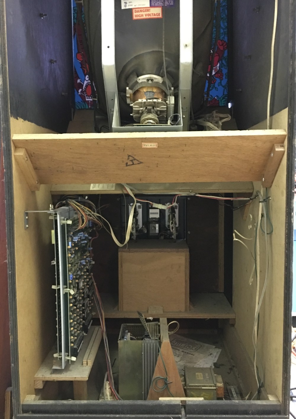
I mentioned earlier in this post that the power supply had ‘popped’ and clearly someone has decided to ‘have a look’:
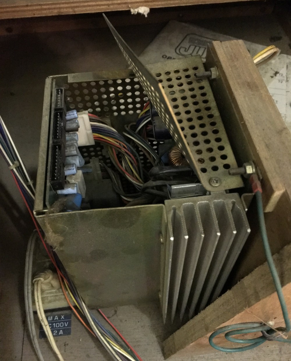
I’ve got the cabinet powered up using a switcher at the moment, so this will come out and be the first ‘victim’ of my first attemp at replacing capacitors. I’m sure the lid will straighten out too with a bit of coaxing.
You’ll notice in the picture above that there’s also a manual in the bottom of the cabinet:
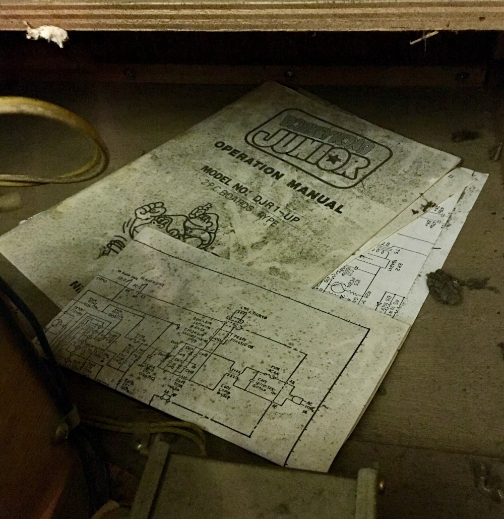
I need to get the hoover in the bottom of this cab, so I’ll rescue these at that point. I’ve learned my lesson in the past with blind hoovering, so I had a quick look around the bottom of the cabinet to see if there was anything loose:

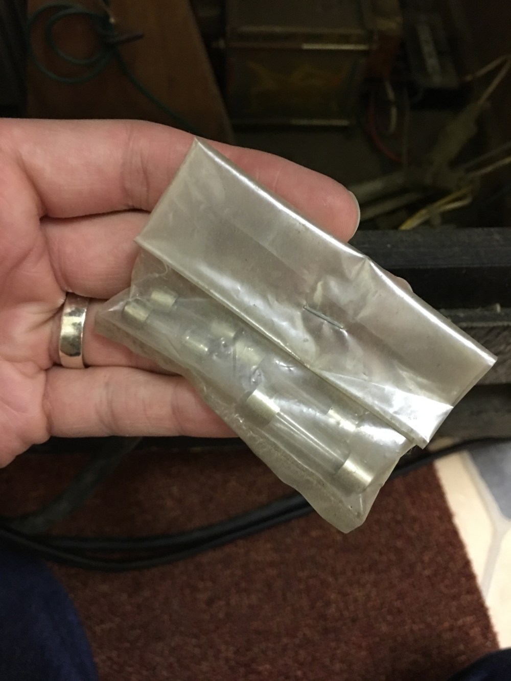
I spied a couple of loose screws in the bottom so used the handily provided drinking straw the have a dig around and see what else was hiding. I came up with some interesting results:
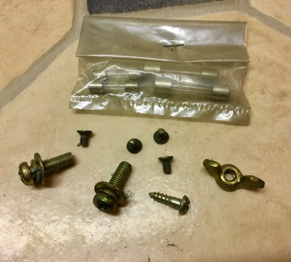
So we have a full set of spare original fuses (that’ll come in handy with the monitor issue we have!), two monitor mounting screws, a wingnut, a screw used in various places throughout the cab and four small screws. The smaller screws intrigued me the most as they looked remarkably like the screws used to attach the restrictor plate to the underside of the joystick. As there are only four screws that hold this plate in place, this warranted a quick flip of the control panel:
Clearly this plate has been moving around for a few years, this has also meant the restrictor plate hasn’t worn like they normally do. As I had the control panel out anyway I thought I’d best put these screws back. Unfortunately, only two of the screws actually had thread on them as two had had the threads worn off completely (most likely the reason they were in the bottom of the cabinet!). I put back what I could until I could get to my parts bin (I have a number of new ones of these screws from MikesArcade):
I put the control panel back and as I went to close the coin door, I noticed the number on the coin counter:
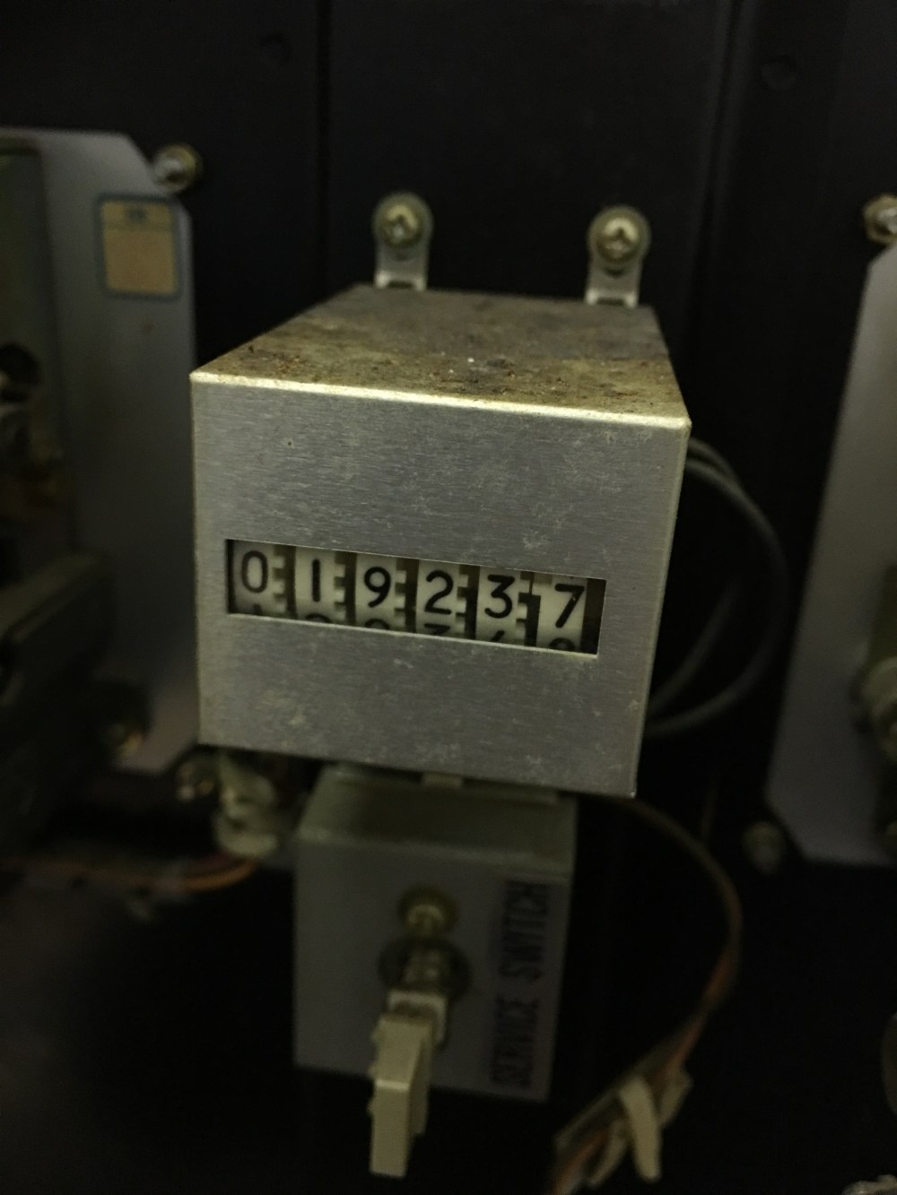
That’s a nice low count, so it’s no wonder the cabinet is in the shape it is.
So that’s where I left things for the evening. With the picture back to where it should be on the monitor meant I could put the cab into the lineup, but I’m going to sort that ‘fuse’ first as I don’t like the way it glows at the moment. Maybe I could make use of another one of my discoveries: